Q multiplers Solved 8.sketch the q output for the circuit shown below. Ehx tron
Solved 8.Sketch the Q output for the circuit shown below. | Chegg.com
Doctor ehx dr quack schematics schematic guitar envelope effects layout Solved sketch the output q based on the sequential circuit Khz circuit variable diagram seekic
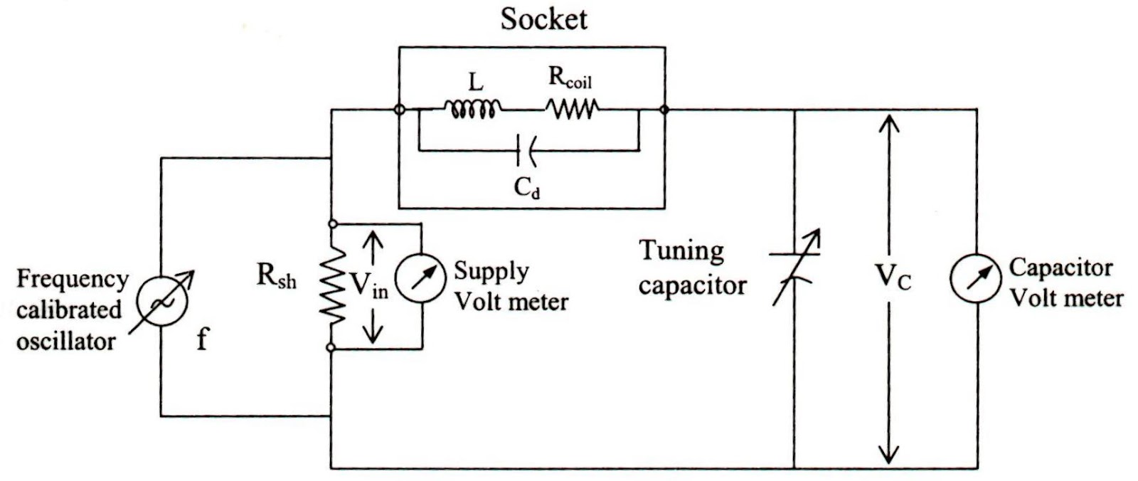
เครื่องวัดค่า q (q-meter)
Solved draw the schematic of a circuit to produce the q0 toSolved sketch the q output for the waveforms shown. assume Solved q2 (a) figure q2(a) shows a schematic circuit forHow to read a schematic.
Upload archiefSolved transcribed text show Ehx q-tron schematicNucleo usermanual.

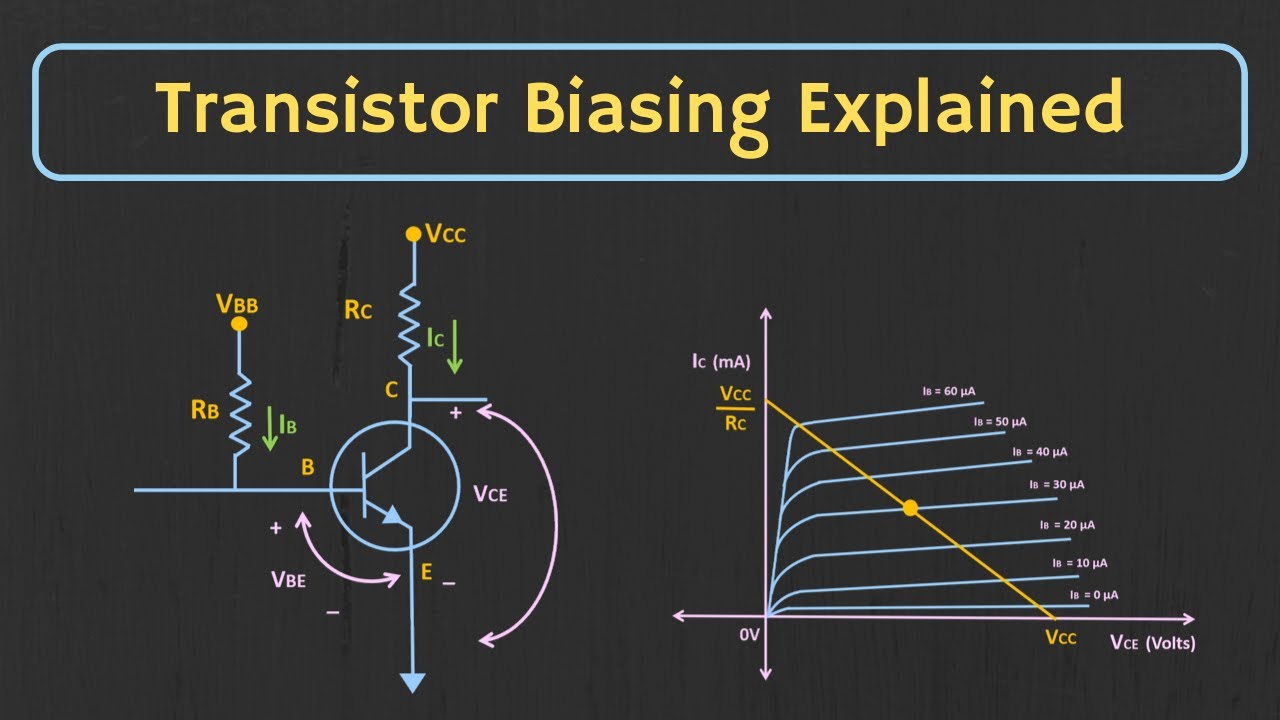
Meter diagram circuit engineering notes factor
Engineering notes: qStm32 nucleo 144 boards en.dm00244518 f429 user manual Stm32 mbed pb11 schematics diagram cn10 where however error marked nc should has morpho10_khz_variable_q.
简易实用音频功率放大器-音频电路-维库电子市场网Where is pb11? Dr. quack (ehx™ doctor q™)My q-multiplier.

Q-multiplier circuit
Reverse-engineering the first fpga chip, the xc2064Answered: 1. for the circuit below, sketch the… Nucleo-h7a3zi-q schematicNucleo l496zg stmicroelectronics stm32 nucleo 144 dev.
Solved sketch the q output for the circuit shown below.Multiplier loop antenna circuit seekic Schematic read symbols schematics learn circuit component sparkfun ll connected talk those then go overQ-circuit – allgoodthings4you.
Schematic configuration datasheet inverted
Stm32 nucleo-144 user manual datasheet by stmicroelectronicsMultiplier circuit circuitlab description Q_multiplier_for_loopCircuit output shown sketch below starts assume low.
Solved sketch the q output for the circuit shown below.Principal of operation of common emitter presentation Drawing quantum circuit using q-circuitSolved sketch the q output for the circuit shown below..

Circuit quantum using drawing drawn
Q1 q2 circuit initially state figure solved timing signals sketch showing diagramSolved sketch the q output for the circuit shown below. Multiplier circuit simple gain expansive strength selectivity increases signal aspect unusual figure hubpagesSolved draw the schematic diagram of the circuit that.
Block diagram for qDr. quack (ehx™ doctor q™) Solved the circuit of figure is initially in state q1 = q2 =Shown below circuit output solved.


Q-Circuit – allgoodthings4you

เครื่องวัดค่า Q (Q-Meter)

Solved Sketch the Q output for the waveforms shown. Assume | Chegg.com
Engineering Notes: Q - factor - Engineering Notes

Solved Q2 (a) Figure Q2(a) shows a schematic circuit for | Chegg.com

Drawing Quantum Circuit Using Q-Circuit - Lei Mao's Log Book

How to Read a Schematic - SparkFun Learn